The Datalogic AREX400 AF is an adjustable-focus fiber laser marking system for permanent Direct Part Marking, serial numbers and traceability codes on metals and suitable plastics. Software-controlled focus adjustment supports stepped components, changing part heights and frequent product changeovers in automotive, electronics and automated manufacturing cells.
The AREX400 AF places text, logos and machine-readable identification directly onto components. Supported marking content includes 1D barcodes, Data Matrix, QR and micro-QR codes, alongside serial numbers and batch references.
Its distinguishing feature is an internal optical Z-shifter: a mechanism that changes the focus distance without moving the complete scanhead. LIGHTER 9 software controls this adjustment, allowing accessible surfaces at different heights to be marked within the selected lens’s working volume.
The lens determines both the marking field and the available height adjustment. The maximum ±60 mm range applies to the 420 mm lens configuration; smaller lenses have different limits.
| Lens / model suffix | Working distance | Marking volume, X × Y × Z |
|---|---|---|
| 160 mm M / MAF | 158 ±20 mm | 90 × 90 × 40 mm |
| 254 mm M / NAF | 261 ±40 mm | 140 × 140 × 80 mm |
| 420 mm L / BAF | 492.5 ±60 mm | 285 × 285 × 120 mm |
Specify the smallest code feature, overall marking area and highest and lowest marking surfaces together. A larger field provides more coverage but also changes the optical conditions, so field size alone is insufficient to select a lens.
A housing with two accessible marking faces 25 mm apart in height may fit within the 160 mm lens’s 40 mm Z range, provided both faces lie inside its permitted working distances. Each mark can use its own programmed focus setting. Sample testing should establish readability and total cycle time at both levels before production settings are accepted.
The pulsed-fibre range comprises AREX410 AF at 10 W, AREX420 AF at 20 W, AREX430 AF at 30 W, AREX450 AF at 50 W and AREX40C AF at 100 W. AREX42M AF provides a separate 20 W MOPA option; MOPA means Master Oscillator Power Amplifier and allows selectable pulse durations for greater control of the marking process.
Source power and lens are configuration choices. Increasing wattage does not establish better contrast or suitability for a heat-sensitive part: material response, pulse settings, required depth and cycle time must be assessed together.
The AREX400 AF manufacturer datasheet provides the source-and-lens order codes, installation dimensions and accessory references.
The AREX400 AF suits component identification in automotive production, industrial electronics, machine tools, precision mechanics and appliance manufacturing. Applications include contrasting codes, engraved identification, logos and annealed marks on suitable metal surfaces, plus marking on selected thermoplastics.
Material grade, additives, coating and surface finish affect the result. Test representative production parts against the required contrast, engraving depth and code readability, including any cleaning, coating or abrasion that occurs after marking.
If an infrared fibre source cannot achieve the required result without unacceptable material changes, compare other laser marking systems with a different wavelength before increasing laser power.
The integrated controller runs LIGHTER 9 on Windows 10 IoT LTSC 2021. It provides layout editing, job execution and diagnostics, with TCP/IP, EtherNet/IP, RS-232 and programmable digital I/O for machine integration. PROFINET requires an additional software licence.
For a PLC-controlled installation, define job selection, variable marking data, trigger signals, busy and complete states, fault handling and the response to a failed code check. Connections to a manufacturing execution system require an agreed data interface and application integration.
MARVIS adds code validation and grading with compatible Datalogic MATRIX readers. It requires a separate licence and reader hardware; select the reader, optics, lighting and acceptance criteria for the actual marked surface. Completion of a marking cycle alone does not establish that the code is readable.
Allow additional clearance for the lens, connectors, mounting hardware and cable routing. Robotic installations must account for the complete mounted load and conduit movement. Machine integration must also address laser containment, interlocks and fume extraction; the embedded Safe Laser Off module forms part of the machine’s safety design.
The Datalogic AREX400 is the nearest alternative when a repeatable fixture presents each part at one marking distance. Both families offer pulsed-fibre power options from 10 W to 100 W and a 20 W MOPA configuration, but their optics and controller specifications differ.
Choose AF when programmed height changes justify the internal focus mechanism. With fixed-focus optics, equivalent changes require positioning the part or scanhead at the appropriate distance. Compare the selected source, lens, code size and tested cycle time rather than assuming equal performance from equal wattage.
AF provides multi-level, or 2.5D, marking within a defined volume. Steeply curved surfaces, tilted faces, obscured areas or height changes outside that volume may require dedicated 3D marking capability or additional part positioning.
Software-controlled focus adjustment uses programmed positions. Automatic compensation for measured height variation requires the optional distance sensor. The documented sensor kit, 93ACC0448, is listed for MAF and NAF models; confirm the sensing arrangement separately for a BAF configuration.
Finished-part throughput depends on the material, artwork, code dimensions, depth, number of passes, focus changes and handling sequence. Establish the complete cycle using production samples, including any reading or validation step. For marking on moving parts, also specify line speed, part spacing and encoder or trigger requirements.
MarvelTech supplies laser marking and industrial automation equipment and offers maintenance, periodic inspections, adjustments and support contracts. Discuss the application review, integration work and ongoing support required for your installation.
The quote depends on the laser source, lens, software licences, distance sensor, validation equipment and accessories, together with any agreed installation and support work. Request confirmation of availability, lead time, warranty terms and service coverage for your location.
Send MarvelTech the material grade and finish, part photos or drawings, marking content and dimensions, required contrast or depth, target cycle time, height variation, available installation space and PLC protocol. Include your installation location and code-quality requirements to request a configuration and quote.
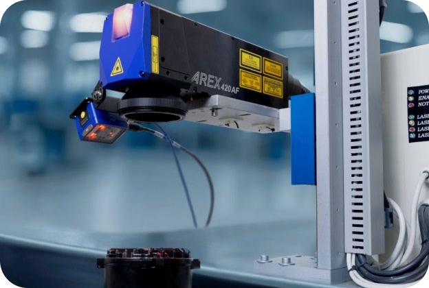
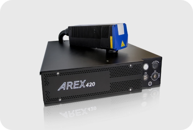
Choose AREX400 AF when different part heights, stepped components or frequent product changes require programmed focus adjustment. Its internal optical Z-shifter changes the focus distance without moving the complete scanhead. The fixed-focus Datalogic AREX400 is an alternative when fixtures consistently present the marking surface at one distance. Compare the complete positioning and marking cycle for your parts.
Automatic height measurement requires an optional distance sensor; the standard adjustable-focus function uses programmed focus positions. Datalogic lists sensor kit 93ACC0448 for MAF and NAF configurations. For a BAF configuration, confirm the sensing arrangement separately. Include the expected height variation and surface finish in the assessment, because the sensor must measure the intended marking surface reliably.
The lens determines the working distance, focus adjustment range and marking volume. With adjustable focus enabled, Datalogic specifies 158 ±20 mm for the 160 mm lens, 261 ±40 mm for the 254 mm lens and 492.5 ±60 mm for the 420 mm lens. These are operating ranges, not positioning-accuracy figures. Select the lens against both the smallest code feature and the required marking area.
AREX400 AF supports 2.5D marking: marking accessible surfaces at different programmed heights within the selected lens’s working volume. This suits stepped components and part variants with different marking levels. Continuously curved surfaces, steeply tilted faces or obscured areas require separate assessment; changing focus does not change the beam’s approach angle or make a hidden surface accessible.
AREX400 AF is intended for marking metals and selected plastics, with suitability determined by the actual material grade, coating and finish. Test production samples for contrast, depth and readability after any subsequent cleaning or finishing. If the infrared fibre source causes unacceptable material changes, assess another wavelength, such as the green or UV options in the Datalogic VLASE laser marker range.
Select the source through material trials and the required marking result. AREX400 AF offers pulsed-fibre versions at 10, 20, 30, 50 and 100 W, plus the separate 20 W AREX42M AF MOPA version. MOPA, meaning Master Oscillator Power Amplifier, provides selectable pulse durations for additional process control. Higher wattage alone does not establish better contrast, finer detail or suitability for heat-sensitive parts.
AREX400 AF uses LIGHTER 9 with an embedded controller for layout preparation, marking control and diagnostics. TCP/IP, EtherNet/IP, RS-232 and programmable digital I/O support machine integration; PROFINET requires an additional licence. Specify job selection, variable data, trigger signals and completion or fault responses. Connecting to a manufacturing execution system also requires agreed data mapping and application logic.
Yes, with a compatible Datalogic MATRIX reader and a separately licensed LIGHTER MARVIS code-validation workflow. The reader, optics and lighting must suit the code dimensions and marked surface. Define whether acceptance requires successful decoding, matching the expected serial number or a specified quality grade. A completed laser cycle alone does not establish that the finished code meets those requirements.
Assess the complete part cycle using representative production samples. Material response, artwork, code size, engraving depth, passes and focus changes all affect marking time. Include loading, positioning, optional height measurement, code inspection and unloading when calculating throughput. For moving parts, also provide line speed, spacing and trigger or encoder requirements so the proposed configuration can be evaluated under the intended operating conditions.
Robotic integration must account for the complete mounted load, optical access and cable movement. The scanhead weighs 3.5 kg without its scan lens and connects through a 3 m robotic-grade conduit. Add the lens, bracket and any sensor or reader when calculating payload. The station also needs suitable laser containment, interlocks and fume extraction, with Safe Laser Off incorporated into the machine’s safety design.
The IP64 scanhead and control rack have different protection levels: the rack is IP31 when horizontal and IP30 when vertical. Locate the rack accordingly and maintain its cooling airflow. Datalogic specifies operation at 5–40°C for 10–50 W configurations, including the 20 W MOPA version, and 5–35°C for 100 W. Assess enclosure temperature under production load rather than relying only on room temperature.
Send material grade and finish, part drawings or samples, marking content and dimensions, minimum and maximum surface heights, target cycle time and code-quality requirements. Include installation space, part handling, PLC protocol and site location. Ask the quotation to identify the source and lens, optional height sensor, reader, software licences, extraction and integration scope. The region-specific mains power cable must also be specified separately.
Datalogic Lighter MARVIS is industrial laser marking software for creating layouts and checking marked traceability codes with compatible Datalogic laser markers and readers. It combines LIGHTER Suite’s editing and laser control with the licensed MARVIS validation feature for Data Matrix marking, component serialisation and automated Direct Part Marking.
See DetailsThe Datalogic VLASE Series is a solid-state laser marking system family for permanent Direct Part Marking, serialisation and coating removal in electronics, automotive, aerospace and general manufacturing. Infrared, green and UV models allow the wavelength to be matched to reflective metals, selected thermoplastics and heat-sensitive components.
See DetailsThe Datalogic UniQ Fiber Laser Marker is a compact 15 W fibre laser marking system for serial numbers, Data Matrix codes and permanent identification on metals and suitable plastics. Its integrated laser source, controller and power supply suit OEM machinery and production cells where space for a separate control cabinet is limited.
See DetailsPlease contact us if you have any questions or comments.


